


 English
 русский
 Español
 عربى



Sheet metal bending is one of the most fundamental processes in metal fabrication. It turns a flat sheet of steel, aluminum, or copper into...
READ MORE

News
Home / News / Industry News / How to Calculate Bend Allowance: The Complete Guide for Sheet Metal Fabrication
How to Calculate Bend Allowance: The Complete Guide for Sheet Metal Fabrication
2026-10-22
Bend allowance is one of those numbers that quietly determines whether a sheet metal part fits the first time or becomes rework on the shop floor. If you have ever looked at a flat pattern and wondered how much material to add at a bend line, this guide will walk you through the calculation step by step. We have spent more than twenty years forming metal components for automotive, home appliance, and kitchen equipment manufacturers, so the formulas presented here are not just textbook theory. They are used every day to produce components that meet tight tolerances and real production deadlines.
What Is Bend Allowance?
Bend allowance (BA) is the arc length of the neutral axis measured through the bend region. When a flat metal sheet is bent, the material on the outside of the bend stretches, while the material on the inside compresses. Between these two zones lies a neutral axis, a plane that keeps its original length during forming. The distance along this neutral axis across the bend is your bend allowance.
Without this value, you cannot determine the correct flat blank size. If the allowance is too small, the finished part will be shorter than expected. If it is too large, you will need to trim the edges. That is why accurate bend allowance calculation is the foundation of any successful sheet metal project, from simple brackets to our metal bending parts.
 Bent Metal Component with Fabric Strap for Precision AssemblyThis durable bent part with anti-slip fabric strap suits machinery, automotive, and outdoor gear. Its precise design ensures easy integration, but accurate bend allowance is vital for correct sizing.View Product →
The Bend Allowance Formula
The standard formula used across the sheet metal industry is:
BA = (π / 180) × A × (R + K × T)
Where:
- A is the bend angle in degrees.
- R is the inside bend radius.
- K is the K-factor.
- T is the material thickness.
The K-factor accounts for the shift of the neutral axis from the material center. It is an empirical value that changes with material type, thickness, and forming method. As a starting point, many manufacturers use K = 0.44 for air bending of mild steel when the inside radius is close to the material thickness.
Step-by-Step Calculation Example
Let's apply the formula to a common scenario. Suppose you are bending a 2 mm thick steel sheet to a 90° angle with an inside radius of 3 mm. For this material and tooling, assume a K-factor of 0.44.
BA = (π / 180) × A × (R + K × T)
BA = 0.017453 × 90 × (3 + 0.44 × 2)
BA = 0.017453 × 90 × (3 + 0.88)
BA = 0.017453 × 90 × 3.88
BA = 1.5708 × 3.88
BA = 6.09 mm
So the bend allowance for this bend is 6.09 mm. To find the flat blank length, you would add this value to the straight sections of the part while subtracting any outside setbacks if you are working with a bend deduction method. The same formula works for any angle, as long as you keep the units of radius and thickness the same.
Bend Allowance vs Bend Deduction
In sheet metal design, bend allowance and bend deduction are often confused. Bend allowance is the arc length added to the flat pattern to account for material in the bend. Bend deduction, on the other hand, is the amount subtracted from the total of the outside dimensions of the two flanges to get the same flat length. Both methods work, and many CAD systems let you switch between them. The key is to keep your equations consistent.
For example, if you have two flanges with outside dimensions L1 and L2, the flat blank length can be expressed as L1 + L2 - BD, where BD is the bend deduction. The relationship between BA and BD becomes important when you import a part model into a bending simulation or a CNC press brake program. Using the same K-factor for both ensures your flat pattern remains accurate.
K-Factor Values and Material Considerations
Choosing the right K-factor is just as important as applying the formula. The values are affected by material hardness, bending method, tooling radius, and whether the bend follows or crosses the rolling grain direction. The table below shows typical ranges for common materials, but they should always be verified with test bends.
| Material | K-Factor Range | Typical Air Bending Start Point |
|---|---|---|
| Mild steel | 0.33 – 0.45 | 0.44 |
| Stainless steel | 0.30 – 0.40 | 0.38 |
| Aluminum | 0.40 – 0.46 | 0.44 |
| Copper and brass | 0.35 – 0.50 | 0.47 |
These ranges are not universal. A press brake with a polished punch, for instance, may produce a slightly different K-factor than a die with a worn radius. The table gives you a practical starting point, but the most reliable approach is to run a small sample bend and measure the result before programming the production run.
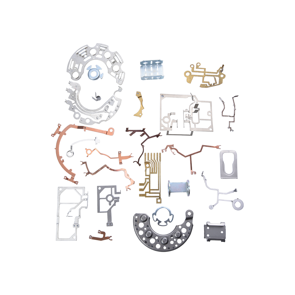
In production, we use this verification method for every new tool set. It is also why our precision metal stamping parts come out consistently within tolerance.
Practical Tips for Production
Calculating bend allowance correctly saves time, material, and frustration. Here are some production floor tips we have learned from forming simple brackets and complex enclosures over the years.
- Check the actual inside radius. The radius in your CAD model may not match the radius created by the tooling. Measure the real radius and use that in the formula.
- Use a consistent bend deduction table. Once you have verified K-factors for your materials, store them in a shared table so estimators and programmers use the same values.
- Account for springback. Most materials spring back slightly after pressure is released. You may need to over-bend slightly, and that changes the effective bend angle used in the formula.
- Watch the grain direction. Bending parallel to the rolling grain can cause cracking, especially on sharp radii. The K-factor remains useful, but the forming method may need to change.
- Keep the tooling clean. A small burr or chip on the die surface can alter the bend behavior and make your bend allowance calculation less accurate.
Many of the components we produce start as flat blanks that are cut, formed, and sometimes assembled with additional attachments. This is particularly true for stamped parts that include bending operations. The calculation method you use will influence every downstream step, from how the part sits in the die to how it performs in the final product.
 Customizable Bendable Stamped Strips for Industrial FlexibilityThese rust-resistant strips offer bending adaptability and strength for various structures. Custom length, thickness, and finish are available, yet proper K-factor verification remains essential when forming them.View Product →
Common Mistakes to Avoid
One of the most frequent errors in bend allowance calculation is using a fixed K-factor for every material and radius. A single value may work for one job, but it will not hold for another. Always confirm the K-factor with a trial bend, especially when you change material thickness or bend radius.
Another mistake is ignoring the difference between the inside radius in the CAD model and the actual radius produced by the tooling. In air bending, the inside radius is often determined by the width of the die opening rather than the punch tip. If you enter the design radius into the formula, your bend allowance may be off by a small but meaningful amount.
Finally, do not forget to account for bend orientation relative to the rolling grain direction. A material with a lower K-factor across the grain may behave differently than one bent parallel to it. The formula is still useful, but the forming parameters may need to be adjusted to avoid cracking or inconsistent angles.
Final Thoughts
Bend allowance calculation is not complicated once you understand the variables. Start with a reasonable K-factor, verify it with test bends, and apply the formula consistently. The small effort you put into accurate bend allowance will pay off in fewer rejected parts, smoother production, and a better-looking final product.
If you are working on a new sheet metal part and need a manufacturer with experience in bending, stamping, and deep drawing, our engineering team is ready to help. We produce custom components from your print or CAD model, and we make sure the bend allowance is right before any tool is cut.
Previous Post
No previous article
Next Post
How to Bend Sheet Metal: A Complete Practical Guide for Precision Results
News
-
-
Every time you slide a tray into an air fryer, bolt a bracket beneath a dashboard, or snap a cover onto an electrical enclosure, you are ho...
READ MORE -
If you have ever asked yourself, “How do I find a reputable metal fabricator?” you are not alone. As a manufacturer with more than 20 years...
READ MORE -
Metal stamping is the process of placing flat sheet metal—either in blank or coil form—into a stamping press, where a tool and die surface ...
READ MORE
Get Fresh Updates Via Email
We promise we will never disclose your email address, and you can opt out at any time.
-
Quick Links
Home About Us Products Service News Contact Us -
Product list
Deep-drawn parts Stamped parts Bending parts Kitchen appliance accessories Automotive stamping parts -
About Us
Factory Honour FAQ -
News
Company News Industry News -
Contact Us
Address: South side of Shunke Road, Yangming Science and Technology Industrial Park, Yuyao City, Zhejiang Province, China Tel: +86-13905842349/+86-13738485724 Email: hongli@hl-stamping.com
Copyright © Yuyao Hongli Optoelectronics Co., Ltd. All Rights Reserved.
Custom Precision-Sheet/Sheet Metal Stamping Manufacturers
