


 English
 русский
 Español
 عربى
عربى
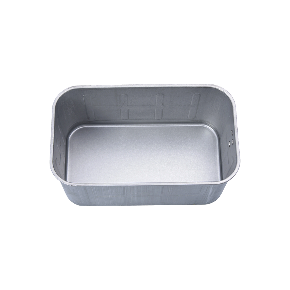
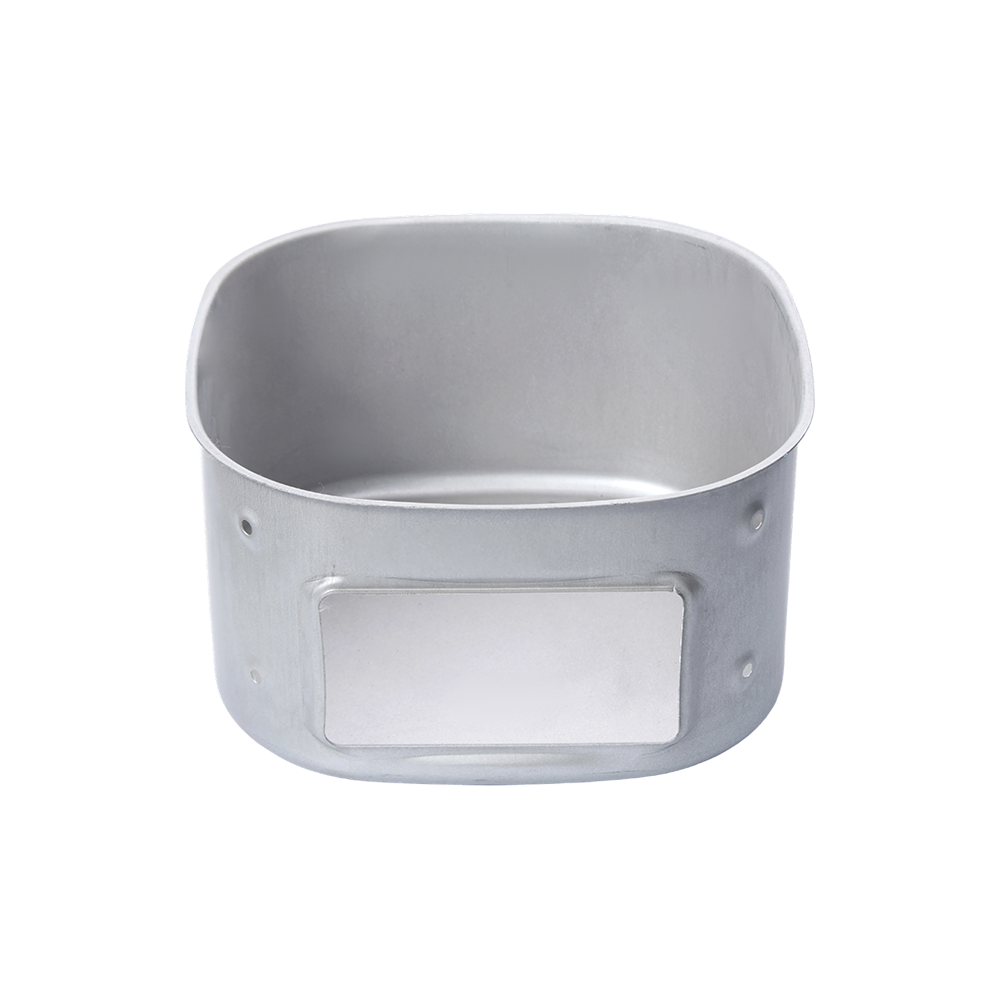
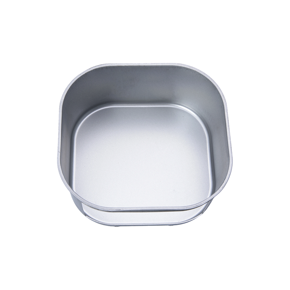
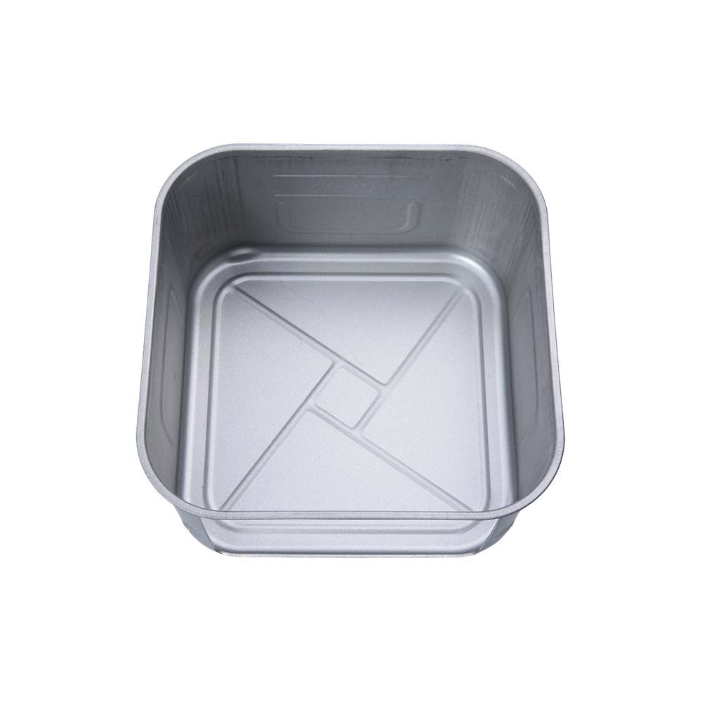
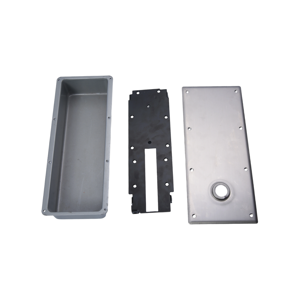
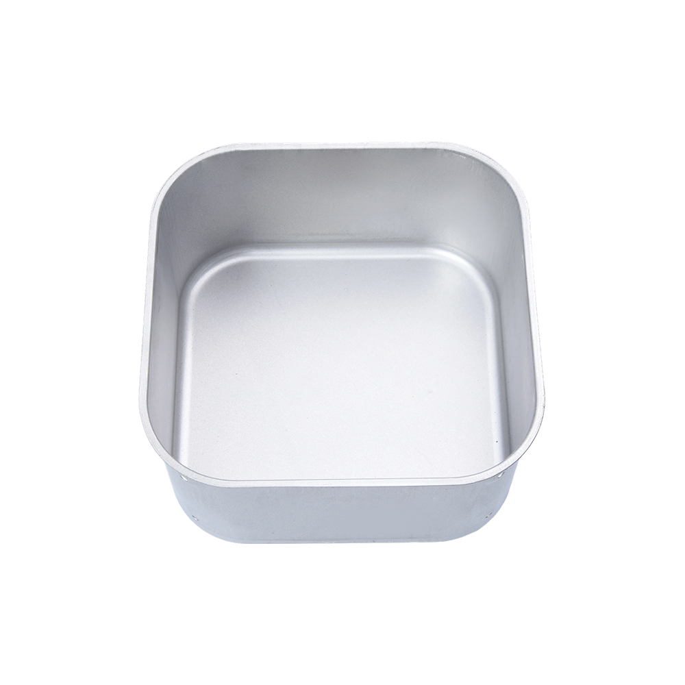
When you need a metal component whose depth clearly exceeds its width, such as a one-piece battery enclosure, an air-fryer inner container,...
READ MORE

News
Deep-Drawn Parts and What Is Deep Drawing Process
2026-08-20
What Is Deep Drawing Process and What Are Deep-Drawn Parts
The deep drawing process is a sheet metal forming operation in which a flat metal blank is pressed into a die cavity by a punch to produce a hollow, cup-shaped or box-shaped component whose depth exceeds its diameter or shortest plan dimension. The "deep" qualifier distinguishes it from shallow drawing (where depth is less than half the diameter) by the degree of plastic deformation applied to the metal and the complexity of the force management required to prevent failure during forming. The finished products of this process are called deep-drawn parts.
Deep-drawn parts are among the most geometrically precise and structurally consistent components produced by any mass-production manufacturing method. Because the entire part is formed from a single continuous sheet of metal without welding, joining, or casting, deep-drawn parts have no seams, no porosity, and no grain boundary discontinuities that would create weak points in the component wall. Deep-drawn parts are produced at rates of 20 to 1,000 parts per minute on modern progressive die systems, making the process the dominant production method for high-volume hollow metal components in the automotive, packaging, electrical, and consumer goods industries.
Common examples of deep-drawn parts encountered in everyday life include: aluminum beverage cans (the cylindrical body is a single deep-drawn aluminum shell), stainless steel kitchen sinks, automotive fuel tanks, battery casings, cartridge brass shell casings, and the housings of electric motors and compressors. In all these cases, the deep drawing process provides the finished component's shape, wall thickness, dimensional accuracy, and surface finish in a single or multi-stage forming operation without material removal.
What Is Deep Drawing Process: The Mechanics and Physics of Sheet Metal Flow
Understanding what is deep drawing process at the mechanical level explains why the process is capable of forming complex three-dimensional shapes from flat sheet and why specific tooling, lubrication, and material properties are required to prevent the failure modes that limit deep draw depth.
The Four-Component Tooling System
Every deep drawing process requires four functional tooling components whose precise geometry and relative motion determine the shape, wall thickness, and quality of the resulting deep-drawn parts:
- Punch (male tool): The solid metal cylinder or shaped tool that pushes the flat metal blank downward through the die opening. The punch outer diameter defines the internal diameter (or internal profile) of the finished deep-drawn part. The punch is hardened steel and pushed downward by the press ram at a controlled velocity during the draw stroke.
- Die (female tool): The ring-shaped or profiled cavity that surrounds the punch and receives the blank as it is drawn downward. The die inner diameter is slightly larger than the punch outer diameter by one material thickness on each side, creating a controlled annular gap through which the metal flows to form the component wall. The die entry radius is critical: too sharp a radius causes tearing; too large a radius reduces drawing force efficiency.
- Blank holder (binder ring): A ring-shaped pressure plate that holds the outer flange of the metal blank against the die face with controlled force during the draw stroke. The blank holder force is the most critical process variable in deep drawing: insufficient blank holder force allows the metal flange to buckle and wrinkle as it flows inward under the radial compressive stress of the draw; excessive blank holder force locks the flange against the die and prevents metal flow, causing the punch to tear through the partially formed cup wall rather than drawing the flange material through the die gap.
- Press and ram: The mechanical or hydraulic press that drives the punch through its stroke and controls the blank holder force. Modern deep drawing presses are servo-driven, allowing the punch velocity and blank holder force to be programmed as continuous functions of punch position rather than fixed values, optimizing the forming force profile for minimum tearing and wrinkling risk throughout the full draw depth.
What Happens to the Metal During the Deep Drawing Process
The metal blank undergoes a complex stress state during the deep drawing process that differs from all other forming operations and determines why deep-drawn parts have their characteristic properties:
- Flange zone (radial tension + circumferential compression): The annular flange of the blank (the material outside the punch contact area) is simultaneously pulled radially inward toward the die opening by the punch tensile load and compressed circumferentially as the same material must reduce in circumference as it flows from the larger blank diameter to the smaller die opening diameter. This biaxial stress state causes the flange material to thicken slightly as it flows inward (the circumferential compression reduces the flange width, which is accommodated by the material thickening in the perpendicular direction).
- Die radius zone (bending and straightening): As the flange material flows over the die radius and bends downward to form the cup wall, it undergoes bending deformation. As the same material continues to flow, it is straightened from the bent configuration into the vertical cup wall orientation. This combined bending-and-straightening cycle work-hardens the material in the die radius zone, which is why the wall of a finished deep-drawn part typically shows slightly higher hardness than the base material.
- Cup wall zone (thin-walled tube in tension): The already-formed wall of the cup is in pure axial tension as it transmits the punch drawing force from the punch face to the flange. This is the most critically loaded zone in deep drawing: if the drawing force exceeds the tensile strength of the wall material (multiplied by the wall cross-sectional area), the wall tears at the punch corner radius, producing a scrapped part. The drawing force limit is why multi-stage drawing (redrawing) is used for deep-drawn parts whose total draw depth exceeds the single-stage capability.
The Draw Ratio: Defining the Limit of Single-Stage Deep Drawing
The draw ratio (DR) is the fundamental parameter that defines what is achievable in a single stage of the deep drawing process and therefore how many drawing stages a specific deep-drawn part requires:
Draw Ratio (DR) = Blank diameter (D0) divided by Punch diameter (dp)
The limiting draw ratio (LDR) is the maximum draw ratio achievable in a single stage without tearing the cup wall, and it depends on the material's plastic anisotropy (its tendency to thin uniformly rather than necking locally when stretched). For low-carbon deep-drawing steel, the LDR is approximately 2.1 to 2.3; for aluminum alloys, it is 1.9 to 2.1; and for stainless steel, it is approximately 1.8 to 2.0. A deep-drawn part requiring a blank diameter of 200 mm to produce a 50 mm diameter cup would have a draw ratio of 4.0, far exceeding any single-stage LDR and requiring three or more progressive drawing stages to achieve the final depth.
Materials Used to Produce Deep-Drawn Parts: Selection Criteria and Performance
The material selection for deep-drawn parts is determined by the required mechanical properties, corrosion resistance, and formability of the finished component. Not all metals can be deep drawn, and among those that can, the achievable draw depth, wall thickness uniformity, and surface quality vary significantly with material grade and temper.
Deep Drawing Steel: The Most Widely Used Material
Low-carbon drawing quality steel (designated DC01 to DC06 in the EN 10130 European standard, or SPCC to SPCG in the JIS standard) is the material most commonly used to produce deep-drawn parts in the automotive, appliance, and packaging industries. The DC04 and DC05 grades (designated as "drawing quality" and "extra deep drawing quality" respectively) have been specifically developed for the deep drawing process with controlled chemistry and annealing treatments that maximize the plastic anisotropy ratio (r-value) of the steel:
- Normal anisotropy ratio (r-value): A material property that describes the ratio of plastic strain in the width direction to plastic strain in the thickness direction during a tensile test. Steel with a high r-value (above 1.5 for DC04, above 1.8 for DC06) resists thinning much more strongly than it resists width reduction, which translates into deep-drawn parts with more uniform wall thickness and resistance to wall tearing during forming.
- Thickness range used in deep-drawn parts production: 0.5 mm to 4.0 mm, with 0.8 mm to 2.0 mm being the most common range for automotive body panels and appliance housings.
Aluminum Alloys for Deep-Drawn Parts
Aluminum deep-drawn parts are produced primarily from the 1000-series (commercially pure aluminum), 3000-series (aluminum-manganese alloys), and 5000-series (aluminum-magnesium alloys) in the annealed or half-hard temper. The aluminum beverage can is the world's highest-volume deep-drawn part: approximately 300 billion aluminum cans are produced annually worldwide, each formed by a two-stage draw and iron (D&I) process that thins the can wall to approximately 0.1 mm while maintaining the base thickness at 0.25 mm, demonstrating the extraordinary precision achievable in aluminum deep drawing at scale.
Stainless Steel Deep-Drawn Parts
Austenitic stainless steel grades (304, 316, 316L) are used for deep-drawn parts requiring corrosion resistance in food processing, medical device, chemical processing, and marine applications. Stainless steel is more challenging to deep draw than low-carbon steel because its higher strength requires greater forming forces and its tendency to work-harden rapidly means the material becomes progressively harder to form as the draw depth increases. Intermediate annealing between drawing stages is often required for deep-drawn parts in stainless steel with draw ratios above 2.0.
Material Comparison for Deep-Drawn Parts
| Material | Limiting Draw Ratio (LDR) | Key Advantage | Key Challenge | Typical Deep-Drawn Part |
|---|---|---|---|---|
| DC04 low-carbon steel | 2.1 to 2.3 | Excellent formability, low cost | Requires painting or plating for corrosion resistance | Automotive body panels, appliance housings |
| 3104 aluminum alloy | 1.9 to 2.1 | Low weight, natural corrosion resistance | Lower LDR, springback management | Beverage cans, aerospace skins |
| 304 stainless steel | 1.8 to 2.0 | Excellent corrosion resistance, hygienic surface | Rapid work hardening, higher tool wear | Kitchen sinks, medical containers, chemical vessels |
| Cartridge brass (70/30) | 2.1 to 2.3 | Excellent formability, good machinability | Higher material cost, limited strength | Ammunition casings, electrical connectors |
| Titanium (Grade 1) | 2.0 to 2.2 | High strength-to-weight, biocompatible | Requires warm drawing, high tool cost | Aerospace components, medical implant housings |
Deep-Drawn Parts: Industries, Applications, and Why the Process Is Selected
Deep-drawn parts appear in virtually every industrial sector that requires hollow metal components in volume, but the process is selected over alternative manufacturing methods (casting, machining, hydroforming, tube forming) based on specific technical and economic criteria that favor deep drawing in particular application profiles.
Automotive Industry: The Largest Consumer of Deep-Drawn Parts
The automotive industry produces more deep-drawn parts per vehicle than any other single industry, with a typical passenger car containing 150 to 200 individual deep-drawn metal components ranging from body panels and fuel tanks to bearing housings, motor cups, and fastener preforms. The automotive application of deep-drawn parts exploits three core advantages of the process:
- Structural integrity without seams: An automotive fuel tank drawn in two halves and welded produces a weld seam that is a potential leak point over the vehicle's service life. A deep-drawn fuel tank formed in a single piece (or as few joined sections as possible) eliminates internal seam corrosion and reduces leak risk significantly. The same principle applies to automotive door panels, where the fewer the seams, the better the panel's long-term performance in a corrosive road environment.
- Consistent wall thickness for crash management: Modern automotive structural components (A-pillars, B-pillars, floor pan sections) use drawn steel panels with precisely controlled wall thickness variation to ensure predictable energy absorption in crash events. The deep drawing process produces wall thickness variations of less than 5% across the panel in well-controlled tooling, which is critical for accurate crash simulation and passive safety engineering.
- High production volume at low per-part cost: A single deep drawing press producing automotive door inner panels can output 600 to 800 parts per hour on a well-tooled production die. At automotive production volumes of 200,000 to 500,000 vehicles per year, the capital investment in deep drawing tooling (typically USD 500,000 to USD 2,000,000 per part) is amortized over millions of parts, reducing the tooling contribution to per-part cost below USD 0.50 to USD 1.00.
Packaging: The Highest Volume Application of Deep-Drawn Parts
By total unit count, the food and beverage packaging industry produces more deep-drawn parts than any other sector. The aluminum beverage can, the two-piece steel food can, and the drawn and ironed (D&I) aerosol can body are all deep-drawn parts produced at production rates that dwarf even the automotive industry's volumes. The two-stage draw and iron process for aluminum beverage cans produces a finished can body from a 14.9-cm diameter blank in approximately 0.3 seconds per can, equivalent to approximately 2,000 cans per minute on a single production line, with 30 to 40 production lines running simultaneously in a single canning plant.
Electrical and Electronic Industry: Precision Deep-Drawn Parts
The electrical and electronics industry uses precision deep-drawn parts for motor housings, solenoid bodies, transformer shells, capacitor casings, and relay housings. These applications demand the highest dimensional accuracy from the deep drawing process, typically specifying:
- Diameter tolerance of plus or minus 0.05 mm or tighter for motor and solenoid housings where the rotor-stator air gap is a critical performance parameter directly determined by the housing bore diameter
- Concentricity of housing bore to external diameter within 0.1 mm total indicator runout to ensure that the motor rotor is centered within the stator bore when the assembled motor is running at speed
- Surface roughness below Ra 1.6 micrometres on sealing surfaces where O-ring or gasket face seals are required to maintain IP-rated protection levels
Medical Device Industry: Deep-Drawn Parts in Sterile and Implantable Applications
Medical device deep-drawn parts in stainless steel and titanium include surgical instrument housings, implantable device enclosures (cardiac pacemaker and neurostimulator shells), endoscope outer tubes, and dental implant components. The seamless, smooth-wall geometry of deep-drawn parts is particularly valuable in medical applications because it eliminates the crevices and joints that harbor bacteria and complicate sterilization. Titanium deep-drawn parts for implantable cardiac device housings must meet dimensional tolerances of plus or minus 0.025 mm on critical sealing diameters and surface roughness of Ra 0.4 micrometres or better on external surfaces that contact body tissue, representing some of the most demanding dimensional specifications in any manufacturing sector.
Common Defects in Deep-Drawn Parts and How They Are Prevented
The quality of deep-drawn parts is determined by the balance of forming forces throughout the drawing stroke, and defects arise when this balance is disturbed by incorrect tooling geometry, inadequate lubrication, material variability, or press setup errors. Understanding the common defects and their causes is essential for troubleshooting and for designing a robust deep drawing process.
Wrinkling
Wrinkling occurs when the blank holder force is insufficient to prevent the flange material from buckling under the circumferential compressive stress that develops as the blank diameter decreases during drawing. Wrinkles in the flange are sometimes acceptable if they are smoothed out as the material flows through the die; wrinkles that are ironed into the cup wall produce visible surface defects that are rejected in appearance-critical deep-drawn parts. Prevention: increase blank holder force; reduce die entry radius; increase material thickness within the design allowance.
Tearing (Fracture at the Punch Nose)
Tearing is the most severe defect in deep drawing, producing a fractured cup that is scrapped. It occurs when the tensile stress in the cup wall (which transmits the drawing force from the punch to the flange) exceeds the material's tensile strength at the punch nose radius, the smallest cross-sectional area in the load path. Prevention: reduce blank holder force (which reduces flange friction and therefore reduces required drawing force); increase punch nose radius; add an intermediate annealing stage; reduce the draw ratio by using a larger-diameter intermediate cup in a redraw stage.
Earing
Earing is the formation of periodic peaks (ears) at the top edge of the drawn cup due to planar anisotropy in the sheet material. If the sheet has different yield strengths in different in-plane directions (due to rolling texture), the flange flows faster in the soft directions and slower in the hard directions, producing a scalloped or peaked cup edge rather than a flat top edge. Earing is a material property issue rather than a process issue and is managed by specifying material with controlled planar anisotropy (delta-r below 0.2 for precision deep-drawn parts) or by trimming the cup edge after drawing.
Surface Scratching and Galling
Surface scratches and metal transfer (galling) on the cup wall occur when the lubrication film between the material and the die or punch surface breaks down under forming pressure. Prevention: use appropriate deep drawing lubricants (mineral oil, soap emulsion, or thin-film dry lubricants for precision applications); apply lubricant uniformly to both blank surfaces; maintain die and punch surface finish below Ra 0.2 micrometres; replace tooling when tool surface roughness increases above the specification limit due to wear.
Frequently Asked Questions
1. What is deep drawing process in simple terms?
The deep drawing process is a metalworking method that transforms a flat sheet of metal into a hollow, cup-shaped or box-shaped component by pressing the flat sheet into a die cavity using a punch. The metal flows plastically from the flat blank into the desired three-dimensional shape without cutting or removing any material. The process is called "deep" drawing because the depth of the finished component exceeds its diameter or shortest plan dimension, distinguishing it from shallower forming operations. Deep-drawn parts made by this process include beverage cans, kitchen sinks, fuel tanks, motor housings, and ammunition casings, among thousands of other hollow metal components used across all industries.
2. What are deep-drawn parts and how are they different from stamped parts?
Deep-drawn parts are hollow metal components produced by the deep drawing process, in which a flat blank is drawn into a three-dimensional hollow shape by a punch pressing through a die. The defining characteristic of deep-drawn parts is that the component's depth is significant relative to its diameter or plan dimensions, requiring controlled metal flow from the blank flange into the part wall. Stamped parts, by contrast, are typically flat or nearly flat components produced by punching (cutting), bending, or shallow forming operations that do not produce deep hollow shapes. A car door panel is stamped (shallow three-dimensional forming); the cylindrical housing of the door's window motor is a deep-drawn part. The distinction matters for process selection, tooling design, material requirements, and the type of defects that must be managed during production.
3. What materials can be used in the deep drawing process?
The deep drawing process works with any ductile metal that can sustain significant plastic deformation without fracturing. The most widely used materials for deep-drawn parts include low-carbon drawing quality steel (the dominant material for automotive and appliance applications), aluminum alloys in the 1000, 3000, and 5000 series (used for beverage cans, aerospace panels, and lightweight structural components), austenitic stainless steel grades 304 and 316 (for corrosion-resistant food processing, medical, and chemical applications), cartridge brass 70/30 (for ammunition casings and electrical connectors), copper (for electrical housings and cookware), and commercially pure titanium and some titanium alloys for aerospace and medical deep-drawn parts. The material's limiting draw ratio, yield-to-tensile strength ratio, normal anisotropy, and strain hardening exponent collectively determine its suitability and achievable draw depth in the deep drawing process.
4. How many stages does the deep drawing process require?
The number of drawing stages required to produce a finished deep-drawn part depends on the draw ratio of the final part. A single drawing stage can achieve a draw ratio of approximately 1.8 to 2.3 depending on the material (the limiting draw ratio or LDR). If the required draw ratio of the finished part exceeds the LDR, additional redrawing stages are needed, each reducing the cup diameter and increasing its depth by a controlled amount. As a practical guide, a final draw ratio of 2.0 typically requires one stage; 3.0 to 3.5 requires two stages; 4.0 to 5.0 requires three stages; and ratios above 5.0 require four or more stages, often with intermediate annealing treatments between stages to restore the material's ductility after work hardening in the previous drawing stage. Progressive die systems that perform multiple drawing stages in a single press stroke on a strip of material can produce finished deep-drawn parts with effective draw ratios of 3.0 to 4.0 in a single pass through the tooling, with part transfer between stations occurring automatically with each press stroke.
5. What is the most common defect in deep-drawn parts?
Wrinkling and tearing are the two most common defects in deep-drawn parts, and they are caused by opposite process conditions. Wrinkling occurs when the blank holder force is too low, allowing the flange material to buckle under circumferential compression during drawing. Tearing occurs when the blank holder force is too high (or the draw ratio exceeds the material's capability), causing excessive friction in the flange that prevents material from flowing through the die and forces the cup wall to carry the full drawing force until it tears. The correct blank holder force lies between these two failure modes and must be determined during the tooling tryout stage through systematic blank holder force adjustment while observing the part for the onset of both defect types. In production, press tonnage monitoring and vision inspection systems are used to detect both defect types automatically so that out-of-tolerance parts are rejected and process corrections are made before significant scrap quantities accumulate.
6. Why are deep-drawn parts stronger than equivalent cast or machined parts?
Deep-drawn parts are often stronger than equivalent parts made by casting or machining from solid bar or plate stock for three reasons. First, the deep drawing process work-hardens the metal during forming: the plastic deformation of the material increases the dislocation density in the metal's crystal structure, which increases yield strength by 20% to 60% over the original annealed material depending on the draw ratio and material type. Second, the metal in deep-drawn parts has a continuous grain flow that follows the part geometry without interruption, unlike machined parts whose grain flow is cut by the machining operation regardless of its orientation relative to the applied loads in service. Third, deep-drawn parts have no porosity, no shrinkage voids, and no inclusion-rich zone boundaries that are inherent microstructural weaknesses in cast components. For applications where the deep-drawn part wall is the primary load-bearing element (pressure vessels, motor housings, structural enclosures), the combination of work-hardening and continuous grain flow makes the wall structure substantially stronger than the same alloy in a cast or annealed machined condition.
7. What lubrication is used in the deep drawing process?
Lubrication in the deep drawing process serves to reduce friction between the metal blank and the tooling surfaces (punch, die, and blank holder), which reduces the drawing force required and prevents surface damage (scratching and galling) on the finished deep-drawn parts. The choice of lubricant depends on the material being drawn, the drawing speed, and the surface finish requirement for the finished part. Common lubricants include: mineral oil or petroleum-based drawing compounds for steel; soap emulsions or aluminum-specific drawing oils for aluminum alloys; chlorinated paraffin or sulfurized oils for stainless steel (which requires more aggressive lubrication due to its tendency to gall); and thin-film dry lubricants (PTFE-based or molybdenum disulfide) for precision deep-drawn parts in tight-tolerance applications where liquid lubricants would be difficult to remove completely. The lubricant is typically applied by spraying, roller coating, or dipping the blank before it enters the die, and is removed from finished deep-drawn parts by degreasing (aqueous alkaline cleaning or solvent cleaning) before subsequent surface treatment or assembly operations.
8. How is wall thickness controlled in the deep drawing process?
In standard deep drawing, the wall thickness is controlled primarily by the clearance between the punch and the die (the annular gap through which the metal flows to form the wall). If the clearance equals the blank thickness, the wall is drawn without ironing and retains approximately the same thickness as the original blank with only minor thickening due to the circumferential compression of the flange. If the clearance is deliberately set smaller than the blank thickness, the wall is ironed (squeezed thinner) as it passes through the punch-die gap, producing a wall that is thinner and more uniform than the starting blank. The draw and iron (D&I) process used for aluminum beverage cans combines drawing and ironing to produce a can wall of 0.097 to 0.115 mm from a starting blank of 0.28 mm, a thickness reduction of approximately 60% to 65%. Wall thickness variation across the finished deep-drawn part is the key quality metric: well-controlled deep drawing achieves less than 5% wall thickness variation, while ironing reduces this further to less than 2% in precision applications.
9. What is the difference between deep drawing and hydroforming for hollow parts?
Deep drawing and hydroforming both produce hollow metal components from flat sheet or tube stock, but they differ in how the forming force is applied. In deep drawing, the punch (a solid metal tool) applies a direct mechanical forming force to the blank. In hydroforming, pressurized fluid (typically water or oil at pressures of 50 to 700 MPa) is used as the "punch" to press the blank against the die contour. Hydroforming does not require a physical punch matching the part geometry, which makes it better suited than deep drawing for parts with complex internal features, asymmetric cross-sections, and multiple branches (automotive exhaust manifolds, complex structural nodes). Deep drawing has higher production rates and lower per-part cost for simple to moderately complex symmetric shapes (cups, cylinders, boxes) at high volumes. Hydroforming is more economical for low-to-medium volume parts with geometric complexity that would require expensive multi-piece progressive tooling in conventional deep drawing. Both processes produce seamless hollow parts, but their optimal application geometries do not overlap significantly.
10. What quality standards apply to deep-drawn parts in regulated industries?
Deep-drawn parts produced for regulated industries must meet the quality system and product specification requirements of the applicable standard for their end-use sector. In the automotive industry, deep-drawn parts suppliers operate under IATF 16949 (the international automotive quality management standard), with product-specific dimensional and material requirements specified in the PPAP (Production Part Approval Process) documentation submitted to the OEM before production supply. In the aerospace sector, deep-drawn parts fall under AS9100 quality system requirements with material and process documentation traceability to AS9102 first article inspection requirements. For medical device deep-drawn parts, ISO 13485 (quality management for medical devices) governs the supplier's quality system, with the dimensional and material specifications controlled under a design history file and device master record. In the food packaging industry, deep-drawn parts from aluminum and steel in direct food contact must comply with the FDA (USA) or EU Regulation 10/2011 (Europe) materials compliance requirements for food-contact metals, confirming that the specific alloy and lubricant residue levels do not transfer substances to the food contents above the legally permitted migration limits.
Previous Post
Why might deep draw components outperform fabricated sheet metal parts in leak-proof applications?
Next Post
What Are Stamped Parts? Types, Materials, and Applications Explained
News
-
-
A flat mounting plate with three punched holes and a rectangular container with a fitted lid can come off presses in the same workshop, yet...
READ MORE -
What Are Stamped Parts? Stamped parts are metal components produced by pressing flat sheet metal between a die and a punch to cut, bend, or...
READ MORE -
Sheet metal is one of those materials that quietly holds everyday life together. The tray inside your air fryer, the bracket behind a car b...
READ MORE
Get Fresh Updates Via Email
We promise we will never disclose your email address, and you can opt out at any time.
-
Quick Links
Home About Us Products Service News Contact Us -
Product list
Deep-drawn parts Stamped parts Bending parts Kitchen appliance accessories Automotive stamping parts -
About Us
Factory Honour FAQ -
News
Company News Industry News -
Contact Us
Address: South side of Shunke Road, Yangming Science and Technology Industrial Park, Yuyao City, Zhejiang Province, China Tel: +86-13905842349/+86-13738485724 Email: hongli@hl-stamping.com
Copyright © Yuyao Hongli Optoelectronics Co., Ltd. All Rights Reserved.
Custom Precision-Sheet/Sheet Metal Stamping Manufacturers
